|
Featured build Hangar 9 Mustand d PTS |
Introductions are in order:
In the beginning there was darkness. Man made RC planes and there was light. Man saw that it was good so he made more planes. And more planes. Unfortunately for man his wife was not nearly as excited as he was. The wife came around. She's cool with it now because she always knows were I am. In the garage. In fact she is so cool with my obsession that over the last five years I've been in the hobby I now have a frig, computer, DVD, heaters and TV in the garage. All the comforts of home. Do you think she has a plan?
OK, so it's a strange start to this blog. So what. The whole point of this hobby is to have fun. The point of this blog is to share the fun I'm having with others. I make no assertions that I have all the answers or that I am the go to guy. I just want others to get as much out of the RC plane hobby as I have. If you like what your reading share it with others. If you don't move on.
History:
I built my first model airplane when I was in the fifth grade. One of Guillows small wooden models. I think it was a Jug (P-47) if memory serves. This was back before CA glue and all these awesome iron on coverings we now have. You could glue 3-4 pieces before you had to wait for the glue to set up. It took months to build, but only moment to crash. After I think three different models I finally gave up. Five years ago a buddy of mine got me back into the hobby and I've been manic ever since. I went through several models before I realized I need to learn how to fly. More importantly how to land. Witch brings up the first law of flying:
"Take offs are optional, landings are mandatory" (unknown source)
Here is the first piece of advise I"ll offer any new pilot, or for that matter anyone serious about the hobby. Get a simulator program and learn to fly before you spend hundreds of dollars on models with a life expectancy of about three flights. Great Plane makes an excellent program. I believe it's now called G-5. What makes this program so cool is that not only does it offer countless models to choose from. You can actually redesign the model and change virtually any aspect of the airframe. I use this program to create new airplanes and test fly them in the simulator before building. This bring up the first rule of building:
"Even a brick will fly with enough velocity and thrust" (mine I think)
Shape, weight and power are critical to how well a plane flies so build light, strong and for gods sake aerodynamically. Figure it out in the simulator. It's much cheaper than at the field. Make changes on the bench not the airfield. Of coarse there's much more to it than that, but you get the idea. And now we come to the second rule of flying:
"If it's not working on the ground, It won't get any better in the air" (unknown Source)
If your having a problem with anything on the airplane, don't fly it till you resolve the problem. I can't tell you how many planes I've seen go in because the pilot chose to fly his plane knowing he had an issue. The sound an airplane makes when it hits the ground is one you don't want to hear. Nor do you want to take the walk of shame. Especially when you knew you had a problem before take off. Statistically the greatest reason for a plane to crash is pilot error. I've heard it's somewhere in the order of 90%. I think this might be low. Consider that if the pilot never took off the plane would still be in one piece. I think it's closer to 100% pilot error. Plus or minus 1%.
Building:
Building is not that difficult. It doesn't have to be all that time consuming. It just takes a basic understanding of the elements involved. Why does a plane fly. Why does it fly a certain way, and what can I do to change the way the plane flies. Understand these key elements and you can build most any airframe.
Rule three:
"God grant me the strength to change the thing I can change. Accept the things I can't change and the wisdom to know the difference." (unknown source)
The best advise I can offer if you want to build flyable model planes is to start with ARF's. (almost ready to fly). This is a sure way to gain an understanding of the structure of an airframe and the assembly process. It may seem the long way around but trust me. You will learn a great deal from the assembly experience that you will use later as you scratch build or build from a set of plans. Even precut kits have room for improvements. A good example of this would be a kit that calls for bell cranks to operate the ailerons rather than dedicated servos. Aside from the slop involve with bell cranks there is the added difficulty of making any kind of adjustment once the bell crank is sealed in the wing. Putting your faith in one servo can be chancy under high load conditions. Also it's very difficult to set up any differential with a bell crank system. This is just an example of what you learn from ARF's. Most if not all ARF's use separate servos for each aileron. The time involved to fabricate removable servo covers is actually much less than trying to set up the bell crank system to deflect both aileron equally. Lastly, a heavy duty servo should be used in a bell crank system which could ultimately cost more than two lower torque servos in the dedicated system. So do yourself and the other pilots at the field a favor. Know as much as you can before throwing money at the hobby. Get a simulator and practice until you master the basics of taking off marinating flight as long as you wish and finally landing. By landing I mean to infer, where you intend to land not just were the plan stops.
If you will follow this advice I promise you will have more fun for less money and spend less time coming up with cover stories for why your plane crashed. Eventually you'll Get you AMA license and join a cub. Then the moment of truth. With all eyes on the new guy, you'll taxi out and set up for a take off. Now that little voice in your head starts asking questions. I won't bother with the questions because you already know what they are. The only answer to every question is yes I did, or yes I can. If that's not the answer in your head abort now or forever collect the pieces of you plane. Oh and by the way, the only help you'll probably get is the help you ask for. So ask for help. Pride is very expensive and truly a waste of time.Most people are more than glad to assist, but most don't want to presume you need it. Rule four:
"If you think you may need help, you do" "Ask and ye shall receive"
OK enough preaching, lets talk about building.
You need to decide early on what you power preference will be. By this I mean are you interested in glow, gas or perhaps electric as you choice of motor/engine. Deciding after your build is complete creates a higher degree of difficulty and could scrub a project all together. More on that later. My preference is electric power and I have used it in every plane built for myself. Which in case your wandering is over one hundred thus far and counting. A few examples may be in order here. Hangar 9's PTS Mustang, 60 size p-47, F4U Corsair, and F6F Hellcat to name a few. All with electric power. These are all great e-conversions and I would recommend any Hangar 9 plane for this type of power system. They are well built and have very good off the shelf fling characteristics. Even giant scale can be converted so don't be afraid to by an airplane and install electric power. I'll give lots of examples of what approaches can be taken to install electric power systems.
|
| Ryan STA by Great Planes. Very easy kit to complete; joy to fly |
If on the other hand you have progressed past the point above and wish to start building I would like to recommend a few first projects here. First and foremost start with a good kit. One that is not to detailed or challenging. Great Planes offers excellent kits such as the Slow Poke 40 and the Ryan STA. Both of these are fast build and are currently still available as kits. Priced well witch helps. The Super Chipmunk by Carl Goldberg Models is another kit that was a joy to build. All three of these are eclectic powered and fly fantastic. One thing to keep in mind when choosing a kit, not all kits are equal. Older kits available say on E-Bay or RC Universe can require a great deal more work since laser cutting was not around in the olden days. Also not all companies could replace cutters as they aged so the fit of a lot of the formers may be poor. Not to mention most of the early kits were not designed using Cad design software. So its best to start with name brand manufacturers of kits. At least until you have a few builds under your belt.
|
| Carl Goldberg Super Chipmunk. Fun to build ; a blast to fly |
 |
| Great Planes Slow Poke 40 easy build and easy to fly |
The Lesson:
The first thing when selecting an airplane is very simple. Do your homework before you buy. The guy at the hobby store doesn't have a vested interest in your success. He may not even fly planes and will only be to happy to help you replace plane after plane. That doesn't mean he doesn't care or isn't a great guy. He just can't read minds. Not part of may job description. So know what your looking for before you lay down your hard earned cash. Secondly, start with and airplane that is within your ability. Cool is great but no one likes coming home from the fling field with a pile of balsa and damaged electronics. If you must have cool then ask for help with the maiden flight of your new baby. There is no shame in this. In fact it's the wises decision you may make that day.
Lets build a plane shall we:
As I mentioned earlier all my planes are electric conversions or I designed them for electric power from the start. So that's what we will be working with in this blog. We'll start with ARF's move on to kit builds, building from plans, then true scratch builds. Then the fun really begins. Designing your own air plane.

For our first project I'll assume that you have been practicing flying on you simulator and have found a few favorite planes. One of mine is the Mustang D. This is the plane selected for our first ARF build with e-conversion. The P51 Mustang used is made by Hangar 9 and is a PTS model. (Progressive Trainer System) It is considered a 40 size airframe and all recommendation will be appropriate for a 40-60 size plane.This model can be piloted by almost anyone having flow over wing trainers for a while. It makes an excellent electric conversion. The Mustang pictured has had a few modifications and has had all the PTS accessories removed. More about the modifications later Since this ARF comes with a very good instruction manual I'm going to assume you can follow directions and have the ability to read. This is not about the assembly of your Mustang. It's about how to set it up for your first flight and many flights to come.
|
| The Mustang above is a hybrid of my own design. It combines Hangar 9 PTS wings and tail sections with a scratch built fuse featuring a razor back design. I will be using this P-51 also to illustrate some of the modifications you'll be making for you e-conversion Mustang |
Here's what you want in the way of electronics and power system:
E-Fite 46 BL out runner motor. It provides awesome power. Is reliable and E-flite provides exceptional service should you ever need it.
Castle creations make good ESC's (electronic speed controllers), as do E-flight, Hacker, Scorpion and Venum. Later you will find cheaper electronics, but for now lets go name brand for convenience. We will use a Castle Creations 80 amp speed controller. Even though the recommended speed controller is only a 60 amps.I like to have a margin and it allows me the flexibility of interchangeable components for larger aircraft without the need have to buy more electronics. The Castle 80 amp has the added advantage of being able to handle 6 cell Lipo's witch will come in handy on our next build.
JR makes good servos. We will use the ST 47 BB servo for this project. They have a ball bearing built in for smoother performance and longer life, are reasonably fast and provide plenty of torque for a 40 to 60 size air plane. You will need five servos if you want functional flaps. I highly recommend functional flaps. Very cool and makes landing you Mustang a breeze.
Batteries are the key and you don't have to buy expensive batteries in order to get performance. Battery discharge rates and storage capacity are really what matters. In fact a lot of name brand batteries don't last any longer or perform any better than the cheep ones.
We'll use 5 cell Nano-tec 4000mah 45-90 C rating batteries from Hobby King for this project. These batteries sell for about $60.00. Not bad at all. A similar battery a few years ago would have set you back about $200.00 and still will with some manufactures.
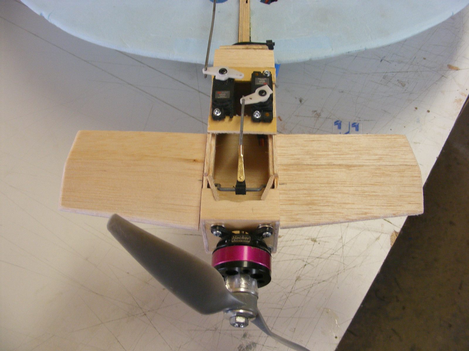
A second battery is needed for the reciever and flight controls. There are two ways to go with this. One is to use a BEC (battery eliminator circet) and a two cell LI-Po with at least 700 mah as your flight pack also available at Hobby King. . The second solution is a five cell Ni Cad pluged directly into the reciever. Available at the local hobby store. In either case make sure you locate the battery as far forwad in the fuse as possible and with easy acess for removal and charging. Take a close look at the photos and you will see a small block of gray foam toward the rear of the opening with a noch cut out. This is the location for a two cell 1300 mah Li-Po used for this aircraft.
Note: If you choose to use a Li-Po battery you will need a BEC (Battery Eliminator Circet). High voltage can damage your receiver and cause flutter and/or damage to the servos.The BEC steps the voltage down for your receiver and servos.A decent BEC will set you back about $20.00. Avoid using Built in BEC's in most Speed controls when possible. If the speed controler fails you may also loose flight control. A seperate power supply to your flight controls is prefered. Even if the motor stops you will still be able to fly the plane to a soft emergency landing.
Gather all this up and I'll continue soon.
Let's continue shall we.
All recommended Modifications should be performed before you start the assembly process
First things first.
Unless you enjoy removing the wing from your plane every time you need to charge the battery(s) I strongly encourage the installation of an access hatch. The best location is on the top of the fuselage with the opening approximately 8.5" from the location of the front of the cowl when installed and approximately 3.25" forward of the instrument cluster. At each of these locations is a light ply former.The size of the access hatch will greatly effect the size of the battery to be used and ease of access. So the larger the opening the less trouble you'll have getting the batter(s) in and out. Unfortunately there are built in limitations with The Hangar 9 Mustang that predetermines the length and width of the hatch. Invert the fuselage and you will see what I'm referring to. In addition to the front and rear lite ply formers there are also side formers to contend with witch will limit the width of the hatch.

Here's the simple solution.
Step One:
Invert the fuse on you work table. Put a small t-pin from the inside of the fuse through the balsa sheeting next to the ply former. Place two additional t-pins approximately 2" from the center pin to both sides. Do this for the front and rear formers. Turn the fuse right side up.Use the protruding ends of the pins as a guide and run a piece of low tack tape between the pins. Make sure the tape is in the inside of the pins relative to the hatch opening to be cut. Do this for front and rear formers. Your mustang comes with black covering on the top of the fuse. Use the black covering as a guide for the side cuts. Using tape along these cuts can help keep you hand steady and your cut strait. Remove all the pins and you will have a pattern to cut out your hatch.
Step Two:
Be careful and go slow. Don't be overly concerned about saving the cut out piece this time. more than likely you'll need to sand the opening after you make you cuts. If you can reuse the cut out section that's great. Remember there is a stringer that will need to be cut through at the center, so again go slow and take your time. If all went well you should have a nice opening in the top of your new model. The opening may have slight over hangs of the formers. That means you did it right. Take a razor blade and put a cut at each corner of the opening. Pull back the covering slightly and sand your opening. Fold the covering over the edge and iron back in place. If you made a perfect cut or are satisfied with the opening and were able to save the piece you removed. the above step is not necessary.
Step Three:

You are now going to create end caps for your hatch.Size two end caps out of 3/32 balsa so that the fit inside your new opening, Make sure the grain is horizontal and that the end caps rise above and drop below the opening so you can sand to shape later. One at a time hold the end caps in place and trace the shape of the respective formers onto the end caps. Mark each cap
front and
rear as well as
inside and
outside to keep them referenced correctly. Mark the center of each end cap and verify the fit. Each end cap should fit and line up with the shape of the formers. Make sure that the caps are below the sheeting used on the model such that when the hatch is sheeted it will be flush with the surrounding surface. Cut a notch in the center of each cap to allow a 1/4 by 1/4 balsa stringer to be installed between the caps.Place clear kitchen wrap at each end of the hatch opening so no glue will contact the surface of your model. Pin the end caps in their respective positions and fit the 1/4 by 1/4 balsa stringer in place. If satisfied with the fit, glue the stringer to the end caps.
Cut two side stringer from 1/4 by 1/4 stock. These stringers will butt up against each end cap at the corners. Insure the fit is snug then glue in place. For those using new material, remove the hatch structure to verify it isn't glued or bound in place. From 3/32 stock cut a section of material slightly lager than the hatch structure to allow for sanding and adjustments. The grain should be directed fore and aft to allow for ease of bending. Place your hatch structure on you build surface and note whether it sits flat on the surface. If it is not flat do not make adjustments. This is the shape of you opening and the hatch is a custom fit so live with it. Instead shim were needed so you can apply light pressure without distorting the shape. Take your previously cut 3/32 sheeting and spray both sides with Windex or some other Alcohol based cleaner. This will allow the material to bend more easily. Once satisfied that the material is a good fit glue the 3/32 balsa to you structure.
Note: If you are using the cut out section do not install it yet. Remove the covering and discard Wait till you have your side stringer installed then text fit before gluing. Remove the structure to insure it is not glued in place and that it is not binding, then reinsert in the opening. Make any adjustment to the strings ie. sanding etc... then glue you cover in place.
Step Four:
Some sanding will need to be done for a tight smooth fit. Test fit often while sanding. Finish sand with 220 grit. Before applying the covering you need to decide how the hatch will be secured in place. Decision time. Will you use hinges to attach you new hatch or would you prefer magnets. Its up to you. If you choose magnets, some addition material will need to be added to the inside of the hatch for placement of the magnets. Should you select the hinge method I recommend plastic style that can be purchased at your local hobby store. Use Epoxy to secure the hinges in place. One other option exists. You may choose to install a dowel in the front of you hatch and a locking pin in the rear. However some additional adjustments will be required to prevent binding during removal and installation of the hatch. At this point I would recommend one of the aforementioned methods. By the way, use Rare Earth magnets also available at the local hobby store. They are stronger and smaller than conventional magnet available at the local hardware store. Apply your black covering of choice prior to hinging and at any time if using magnets. That's it, you now have a custom access hatch to make battery installation and removal possible. Fly, charge and fly again with no fuss. This drive the glow guys nuts.

Make sure your battery will fit through the opening and slide forward all the way to the firewall. If you purchased the battery previously recommended this should be no problem. Place a thick piece of foam inside and in front of the battery location to insure no damage from rough surfaces or screws will come in contact with your battery. Epoxy Velcro straps to secure your battery after obtaining the proper C o G to insure proper location of the straps.
The Photo to the above and left shows a removable hatch and a larger opening. You may choose to make a larger opening as well but it involves cutting the forward plywood former and could comprimise the integrety of the fuselage.This plane was designed with a reinforced lower fuse section.
Just so you know; when I did this modification for the fist time it took about three to four hours. The next time you do this it won't take you the three to four hours you just spent. I can do this type of modification in about an hour, so hang in there. You can too.
Installing you motor and ESC:
Step One:
The best way to start is by placing the cowl on the fuse in the approximate location where it will later be permanently installed. Don't fuss to much. You will have the ability to make adjustments later. Slide the cowl on the fuse. Place a piece of tape slightly under the cowl on the fuse at the top, bottom and both sides. Mark where the edge of the cowl overlaps the fuse on each piece of tape with a pen or sharp marker. These are your reference points for test fitting after the motor and mount are installed. With the cowl still in place and at your reference points, measure the distance from the firewall to the forward most end of the cowl. This should be approximately 4 1/8 to 4 1/4 inches. Remove the cowl and set it aside.
Step Two:
Install the mounting hardware on your E-flite 46 BL out runner motor. Install the prop adapter on the shaft with the collar on. Place the motor on a flat surface with the mount flush with the surface. You will have to let the shaft overhangs the edge of the flat surface for this procedure. Measure the distance from the flat surface to the forward most location of the prop adapter collar.One you have the measurement. you need to subtract it from the overall measurement of the firewall to the front of the cowl. This will provide the total length of your motor mount. Example Total measurement from the fire wall to the cowl : 4 1/4 minus the length of the motor with adapter 2 1/8 = 2 1/8 long motor mount. Your numbers may very but you get the point. Note: Before building the mount trace the fire wall shape on a scrap piece of paper so you have a reference as to the maximum size of your motor mount one attached to the firewall. Remember the mount must fit inside the cowl and be offset to allow the motor position to line up in center in the forward opening of the cowl.
Step Three:
There are a few options as to what type of mount may be used. Metal motor mounts are available from several manufactures. In this section I will assume you're making your own mount. From a sheet of 1/4 inch lite plywood cut two side pieces per your length measurement (approx. 2 1/4" long and 2 1/4" high) These are your right and left side pieces. From the same plywood sheet cut two pieces at the length of your measurement (approx.2 1/4" by 2 3/4"). These are the top and bottom of your motor mount.
Step Four:
Place all four pieces on edge on your flat surface so that they stand 2 1/4 " high. Over lap the side pieces with the top and bottom pieces.. If all pieces are roughly the same height then mix some 5 minute epoxy for gluing the pieces together. Note: they don't have to be perfect at this point, just as long as the matting surfaces are flush between the top and sides and the mount is reasonably square. Apply epoxy to the matting surfaces and clamp in place. Try to keep it square After the epoxy is set sand the front and back of the mount surfaces flush. Next you need to make the front and rear mounting surfaces. Place you mount on the lite plywood sheet used previously and trace the mount shape on the inside of you mount frame. Mark as front. Do the same for the rear piece. When cutting out both the front and rear pieces stay outside the lines. It's easier to do a little sanding for a snug fit. If you cut on the line or inside the line you piece will be loose or not usable. Once satisfied with the fit of the front and rear mounting plates move on to the next step.
Step Five:
Place each mounting plate on you build surface. Draw a diagonal line from each corner creating an X pattern on the surface of the plate. Drill a 3/4" hole in the center of the front plate to allow the shaft of the motor to fit through. Center the motor on the place and mark where the mount hole are. Drill the mount hole over size so your blind nuts collars will fit snug. Install blind nuts in the holes and tighten the motor in place to set the blind nuts. Carefully remove the mounter without disturbing the blind nuts. Apply a small amount of epoxy to each blind nut careful not to get any epoxy on the nuts.
Place the rear mount plate on your build surface. Drill four hole on the X line approximately 1/4" from the corners. Make these holes so you can push the screws to be used through to holes but not to loose. I recommend size 8 by 1/2 metal screws for this application. You may wish to trim the screws after you have done an initial attachment to the fuse to avoid the screws coming in contact with the battery.
Epoxy front mounting plate in your mount. Do not epoxy the rear plate at this time. Place the rear plate inside you mount temporarily.
Step Six:
Your Mustang comes with the right thrust angle built in but you will need to create a down thrust angle between the mount and the motor. Mount the motor to the motor mount wires facing down.Placing two small washers as spacers between the back of the mount supplied with the motor and the motor mount you just created at the top two screw locations. You now have a down thrust angle to start from. Some adjustments may be needed after initial flight. This must be done before you align the motor and cowl to insure proper center position of the motor relative to the cowl opening. Stand the fuselage on it's tail with the firewall facing up toward you and stabilize the fuse in place.Place the motor mount with motor still attached on the firewall. Slide the cowl over the motor and align on the tape marks on the fuselage you made previously. Verify that the motor protrudes the desired amount for prop and spinner clearance if a spinner is to be used. The best way to get a great alignment is to place the spinner back plate on the prop adapter with the cowl in place. Make adjustments to the motor position using the spinner plate as a guide. When satisfied, carefully remove the spinner plate and the cowl. Do not disturb the motor. With the cowl off trace around the motor mount to mark it's position. Using a 90 degree pick tool mark the mounting hole on the firewall.
Step Seven:
Lift the mount from the firewall and remove the back plate of the mount. Verify the the marks on the firewall line up with the holes in the back plate. Drill undersized holes at each of the marks. Mount your back plate to the firewall with the # 8 screws recommended and trimmed to the proper length. Slide the mount over the back plate, reinstall cowl and spinner back plate to verify proper alignment. If satisfied remove cowl and spinner plate and attach the mount. At this pint you may with to permanently install the mount or may elect to mack it removable. Secure To permanently install simply epoxy the mount to the backing plate. To make your mount removable simply drill holes through the sides and into the back mount plate on you bench prior to mounting the backing plate to the firewall. Mount the back plate and screw on the rest of the mount.
You may choose to add gusset's to this structure to increase strength, but it's really not necessary if you used good plywood. You can also epoxy the back mounting plate in place, but again not necessary.
Step Eight:
Mounting the ESC is very easy. Drill a 3/4" hole in the firewall just below the motor mount to allow the wiring to pass threw This creates ventilation for cooling the ESC and battery. Locate the ESC on the auxiliary mount supplied with your model and attach using Velcro.Make sure the plug in end of the ECS is easy to reach through the hatch opening. Insure the wire to the receiver will reach. There is a place to make an opening in the rear of the fuselage bottom just below the stars and bars sicker located on the side of the fuselage. Remove the covering in this area for improved ventilation.
One final note about this model. Because it's a trainer the landing gear are positioned farther forward to reduce nose over tendencies inherent with War Birds. This is a trade off for ground handling and creates a spring effect on landing propelling the air plane back up off the runway if you come down to heavy. I suggest bending the main landing struts back to reduce the forward angle. Aligne the front edge of the wheels about 1 1/2 inches forward of the leading edge of the wing. This will improve ground handling and reduce bounce up on landings.
That's it. The rest of the model goes together per the instructions Have fun and let me know if this helped.
Below is the Dagger. A combination of many planes. Some of which include the Sea Wind and the Russian SU47
Nabu Fighter concept from
Star Wars Episode 1
 |
| This plane is modeled after what foamy currently avalable? I named it the Razer. It has a 71" w/s |
 |
| Cessna 310Q built from a set plans produced by Royal Models |


 Pink foam works great just keep the w/s short or you'll need to add reinforcing rods


