I first learned about this plane for the first time when I saw it pictured in a RC plane publication.
They were advertising the ARF version new on the market. As I always due, I started researching the model and checking reviews. According to the reviews the model was reasonably well build with no major problems noted. However after an extensive search of independent blogs a come to realize this may not be the case. Many of those who purchased this particular model found the prep work on of the many painted accessories poorly done and the color match not particularly good. Then too, the hardware provided with the model was weak and failed easily. The fit and finish over all was substandard and most people who purchased this model were not very happy. Especially when the price for this model was $399.00. It's my understanding that many improvements have been made since the original the models original release. But to little to late for me. I had moved on to a search for plans with the intent of building my own version.
Below you will see my final rendering. I will be providing some details of modifications as well as build hints to help should you choose to build your own Comet.
The plans for this model were purchased from Ivan Pettigrew. If you have the time I recommend visiting Ivan's site at
http://ivansplanes.com/ . He is an excellent designer and has many unique plane plans available.You may feel the need to make some minor alterations and up dates based on new materials available today. Many of Ivan's plans are hand drawn and rendered years ago. A lot has changed in just the last few years. Electronics, motors and landing gear options to name a few. I'll provide a blow by blow of the modifications as we progress through this and not bore you now with to many details.

As with all my planes this model is configured for electric power. All the set up info is a s follows:
I used 2 E-flite 36 bl out runner motors. These will provide excellent power. Each motor is rated at 700 watts power with the use of 4 cell Li-Po batteries. The motor has a continuous draw of 42 amps with a burst of 60 amp. It's important to decide early on in the build if you will use one battery for both motors. Or one battery for each motor. There are advantages to both.
With a single battery you need to series the 2 ESC's together. A single battery may also require that the battery have larger storage or mah rating. A higher C rating (discharge rating) is needed to provide adequate amperage to both motors. To verify that your single battery can provide ample power use the following calculations. You must know the maximum amp draw of the motors used. In this case the E-flight 32 bl motor has a maximum amp draw at burst of 60 amps. Multiply this by 2 since this is a twin. The total amperage needed will be 120 amps at maximum draw. This means that your battery should deliver a minimum of 120 amp. I say minimum, but really you want a margin of at least 20% so you don't over work your battery. This means available amperage should be 140-150 amps.
To figure out how many amps you battery can deliver is also very easy. Multiply the storage or mah of the battery by the C rating of the battery. This amount is the amperage available. Example: A 4S Li-Po battery with a mah of 5,000 and a C rating of 30 would have 150 amps power. 5,000 X 30 = 150,000.00. Ajust the decimal point. Equals 150 amps.
Lets look at some of the advantages of this configuration.
First and foremost is simplicity. You need only build a single battery compartment. Only one battery access point is required. Weight can be centered within the fuselage to produce latitudinal and longitudinal stability. having the batter location in the fuselage will simplify obtaining proper C of G. Thus reducing the potential of adding weight during balancing. Lastly: weight. and thus wing loading of the model. Typically a single battery pack will weigh less than 2 packs with the same ratings.
Now for the disadvantages. There really is only one. disadvantage. Flight time. With a single battery you may need to keep your flight times between 5-7 minuets. If you want longer fight times just install a battery with a higher mah rating. The great thing is the costs of batteries has come down quite a bit and battery performance has improver greatly in recent years. The Cost of a single battery that meets the requirements of this airplane are now available through countless manufactures at costs ranging from $70.00 to $90.00 If you require a brand name battery the cost can go as high as $250.00 or more. The choice is really up to you. I have never found a need to spend large amounts to get decent performance. Check out Hobby King for some awesome battery prices. Remember one thing. A single battery system requires the battery to have a higher mah rating and decent C Rating sufficient for the particular model requirements.
A two battery system may sound more appealing but does have distinct disadvantages. If one battery fails the plane may; and probably will experience adverse yaw or a wing over death spiral. If enough rudder can be applied quickly a catastrophic result may be avoided. Maybe! Since each battery only provides power to one motor the size of the battery can be much smaller and less costly per battery. However since you need two batteries the cost of both combined may be the same or greater than a comparable single battery. You also have the benefit of charging 2 batteries rather than just one. Then we come to making access available to both batteries. Yes you can locate both batteries inside the fuselage. I strongly encourage this. The alternative is to locate the batteries in each nacelle. ESC manufactures will tell you that the closer the battery to the ESC the better. While this May be true I have yet to have any problem with batteries laced as far as several feet from the ESC. Placing the batteries out in the wing can produce adverse yaw and pitch issues. Not to mention all that weight father from the center line of the aircraft. Think of it this way. The farther out from the center the weigh is positioned the greater effect it will have during a turn or a snap roll. This can severely reduce the planes ability to right it's self after a particular maneuver. The battery weight is thrown outward during maneuvers causing slow or unpredictable flight response. Then there is the balancing issues associated. Weight may need to be added out board to obtain lateral balance. Not all batteries weigh the same. Even if they are the same size and from the same manufacturer variations can occur.
Let's move on.
The ESC's selected are made by Castle Creations. I chose the 60 amp Phoenix ESC. This is the recommended size for the E-flite 32 bl out runner motor. Two ESC's are required. One for each motor. Castle Creations does not recommend using one larger ESC for twin applications. The ESC's are located inside the nacelles. The nacelles are designed to be removed from the wing for access to the landing gear, ESC's and servos. I used a single battery system for this airplane located inside the fuse so no access hatches are Incorporated within the nacelles. This had the added bonus of additional room for the retractable main gear and landing gear servos.
All the servos used are JR ST 47 BB standard. With the exception of the landing gear servos. The are a JR Landing gear servos.
A separate 5 cell Ni Ma battery pack is used to power the electronics A Spectrum receiver system was installed.
That's it. Now we can move on to the build.
Building a wing:
The plans for this model were hand drawn by Ivan Pettigrew. A well know and respected designer. They were somewhat rough in nature but did allow for very easy modifications. All the drawings were on a single sheet so it was necessary to cut each section from the main plan sheet in order to simplify the build process.
You should always cover your plans with a clear wrap or other translucent material to avoid gluing your model to the plans or build surface. As with all scratch builds, you need to cut out patterns from the plan sheet then trace the patters on to the flat sheet stock material. For the wing. cut all of the formers out first. Match each former to its corresponding former for both wing halves. This will insure both wings are the same when completed. I have found a single sided razor blade works best for this. You can get these at your local hardware store. A box of 100 blades cost around$7.00-$9.00
Test fit all the formers over your plans on the main spar prior to gluing. Some adjustments may be necessary so text fit all components first. Use a straight edge to help align the formers to insure a tight fit with the back of the leading edge material and the front edge of the formers.

Once you are satisfied with the fit. Glue all the formers except former one (center former) to the main spar using a square to insure the formers are perpendicular (90 degree angle) to the build. Most wings are designed with dihedral. The number one former(s) (center former) may need to be place at an angle relative to the build surface. Consult the plans and if necessary, create an angle piece (jig) that is appropriate for your model. Use this angle jig to position the center former at the appropriate angle. This model has 2-inches of dihedral. Requiring the center former(s) be placed at an angel. Make certain that all formers on aligned properly over the corresponding locations on the plans. For gluing formers to the main spar I recommend using Medium CA glue. An accelerator may be used but is generally not necessary.

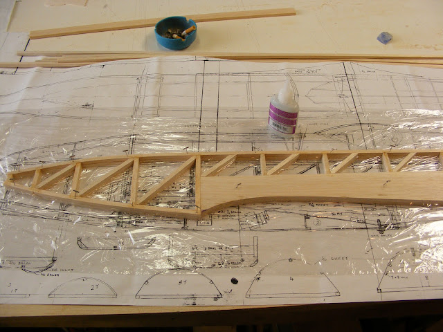
Most sets of plans don't provide the order in which you should build different components. This is up to the builder. I usually build the flight surfaces along with the wing to insure a good fit. As you can see below. This was done for both the ailerons and flaps. The plans for this model didn't have the flaps drawn but I felt they would be very advantageous given the tapered wing design. The flaps I designed deploy between the nacelles and the fuse. This design creates less drag and extends the wing surface affording slower landing speeds. It was only later. After I had completed this build that I learned the original style of flap used on the full size Comet. The original flaps were more of an air brake design. A one piece flap running between the nacelles and under the fuselage. For scale effect I should have done my home work. Oh well better with flaps than without.
 |
| Notice the wing extends straight on the plans. |
Sheeting the flight surfaces once their sub structure is complete makes them much easier to work with and you are less likely to cause damage due to rough handling. Do this as soon as your flight sub structures are completed.

The photo above shows the flap with the bottom sheeting applied.
The photo below is the aileron with the bottom sheeting applied.

The picture below shows the wing with the bottom sheeting applied. The wings design is asymmetrical. This was a great time to stabilize all the formers and insure a good fit with the aileron and flap components. Do not sheet the top of the wings till after the wings are joined. A wing joiner is used and must be installed between the to wing halves on the main spars prior to top sheeting the wing. The picture also shows the leading edge and upper spar installed. It's important to install these pieces prior to sheeting the bottom of the wing. Once the sheeting is installed the wing will become very rigid. Make certain there are no twists in the wing prior to gluing the sheeting in place. Secure the wing flat on your build board prior to gluing the sheeting in place. You can choose to create holes in the formers for servo wiring prior to gluing the formes to the main spar or after the formers are attached and the bottom sheeting is applied.
A 1/2-inch outside diameter piece of aluminum tubing at least a foot long makes a great boring tool for this purpose. Place the 1-ft aluminum tube in a vise and rough up the end with a hack saw to create a cutting surface. Place the cutting end of the tube against the former and rotate back and forth in a drill like manner. This will produce a nice clean hole for your wiring to slide through. All the holes will line up perfectly using this method. Work your way through as many formers as needed to reach the farthest servo location.
Just don't forget to make these holes before the top sheeting is applied or you won't be able to feed your servo wires through the wing.

You will notice, long wing formers were created for the center section. This is a deviation from the original plans. The plans call for the center wing extender sections (fillets) to be attached to the fuselage. If you have ever tried to get the fillets of any size to be flush between the wing and the fuse you know the challenges involved. I elected to make the center extension section a part of the wing. The plans also indicate the wing will be permanently attached to the fuselage. I prefer a removable wing configuration for ease of transport and repairs as needed.
Note: See photo of the plans above. Notice that the wing drawing shows the trailing edge of the wing extending straight to the fuse.
This modification makes removing the wing very easy and accelerated the build considerably. Smaller wing fillets were built and attached to the fuse for a smooth scale transition. Two other deviations were incorporated. The first is the use of 3/32 balsa flat stock for the wing formers rather than the 1/16 balsa material indicated on the plans. The 3/32 balsa material was much easier to work with and far less fragile. Secondly, I prefer a fully sheeted wing. Sheeting the wing adds a great deal of strength while creating a sooth scale appearance. Ivan Pettigrew designed this model to be very light. Although these modifications added weight to the model. The over all finish justified the alterations. You be the judge.

I have mentioned before that I prefer ease of operation and access to components within the model. I took a note from ARF's I've assembled and incorporated access doors for the servo(s). The best way to create these doors is while the wing is still on the built board. Measure and cut the doors before cutting out any sheeting on the wing. I recommend using 2/32 light ply for your access doors. If you like, you may want to laminate 1/16 sheeting to the outer surface of the doors. This is helpful when doing the final sand on the wing. The doors will have the same surface density as the surrounding wing and will sand flush much easier.
Once the doors are the desired size and fit snug between the formers. Use the doors as a template to draw the pattern on the inside of the wing sheeting. Cut out the door patterns from the inside of the wing. Stay inside the pattern lines or your opening will be too large. Install mounting rails or other material for the access doors to attach to. Place the doors in the appropriate openings and pre drill the holes for the mounting screws. Mark each door with its location and indicate which edge faces forward. This will insure a good fit later. Using a servo as a guide, mark the opening for the servo arm and mounting blocks. Cut out the servo arm opening. Epoxy the servo mounting blocks in place. Doing all of this before applying covering insures all your parts fit well and no epoxy gets on the covering. Temporally mount the servo to your servo door and test fit in the opening to insure there will be no interference. Install mounting screws and snug them down. If your satisfied with the fit, remove the doors and detach the servo(s).
Build the other half of the wing in the same manner and to the same point of completion.
Once you have both wing halves completed. It's time to join the wing halves together. First test fit to insure proper fit and alignment. Place one wing halve flat on your build surface and secure in place. Place the other wing halve in position and support the outer wing with a block of balsa or a wing jig if you happen to have one. Use small clamps to hold the wing halves together. If the fit is good remove the clamps and lift the unsecured wing off the build surface. Apply epoxy to both inner wing formers and to the wing spars were the wing joiner will attach. Place the wing half back in position and clamp in place. Install the wing joiner and clamp in place. Let the epoxy cure over night.
You may now sheet the top of the wing. Place the wing back in the build surface and secure one side in place. This will be the side to be sheeted first.
Laminate the stock sheeting material being used together prior to attaching to the wing formers. Sand smooth after gluing. Cut the sheeting material to the proper shape but slightly oversize. This will allow for slight adjustments as may be needed for proper fit. Test fit your material prior to gluing and make any adjustments required. When you are satisfied, run beads of Medium CA glue on all the surfaces to be glued. Quickly place your sheeting on the wing and apply pressure to the entire surface. Move you hand over all the wing surface insuring contact between the formers and the sheeting is good. Once the glue has dried you may remove the wing from the build surface and inspect for any gaps at the glue joints. Apply additional glue if required. Sand off any excess material, but don't sand the wing surfaces at this time. Repeat this process for the other wing half. You should now have a completed wing.
Do not finish sand the wing yet.
A Fuselage is born:
Building the fuselage was very straight forward and required no special skills. Built one side first. Cover that side with clear wrap and built the other side on top of the first. This insures that both sides of the fuse come out the same. Seen below with both halves. One on top of the other.


The result: The two fuse halves are as close to the same size and shape as possible.


As you can see by the photo below, I cut out the fuselage upper contoured formers from the plan sheet. Traced them onto 3/32-in flat stock and cut them from the flat stock material. Next, pre-cut 1/4 by 1/4 lower formers from 36-in by 1/4 by 1/4 stock strips. Draw a center line on the plans down the fuse top view section. Place both sides of the fuse on the build board over the plans. Pin each side of the fuse at the front and rear of the wing saddle only. Pin the end of each fuse section to counter-part section. Keeping the top and bottom of each flush with the other. Insure that both fuse halves are perpendicular to the build surface. Keep it true and free of warps. Once satisfied with the placement of the main structure. Install the 1/4 by 1/4 bottom stringers and the corresponding top formers. Install the upper and lower fuse formers in succession. Start at rear of the wing saddle and work toward the tail first. Do not glue any of the formers untill you have all the rear section formers installed. Top and bottom. Check the alignment to make certain the fuse is still centered over the plans and that it is still perpendicular to the build surface. Once satisfied apply thin CA glue to all the matting surfaces except for the end verticle formers. A spacer will need to be place between these (see plans) then glue them and the spacer together.

Follow this same procedure for the formers starting from the rear of the wing saddle moving forward to the front of the saddle. When satisfied with the fit and placement on the plans. Glue with thin CA . Next come the tricky part. Place the forward most formers in place on the front of the fuse but do not glue at this time. Use a rubber band or soft clams to bring the two fuse halves together. Secure the front halves in their proper positions then proceed to installing the remaining fuse formers in place. Once all the formers are in place and you have verified placement and position of the fuse, glue all formers with thin CA. Before releasing the clamps or rubber bands apply medium CA to all previously glued joints and let it cure.
Notice in the photos above and below: The hatch section just above the wing saddle area on the top of the fuselage. The hatch was made at the same time as the rest of the fuse. You can hardly tell it's there. This is by far the best time to make the hatch. You just build the fuse. Then make two extra formers for the hatch ends prior to installing the stringers. This is assuming a hatch is to be installed. Have the stringers installed on the main fuse sections first to stabilise the fuse formers before you move to building the hatch. Cover the inner fuse formers with clear wrap. Place the hatch formers on top of the fuse formers and pin in place. Cut, test fit and glue the hatch stringers in place. Remove the hatch section. That's it. Very simple with a very clean fit. If you like you can install a dowel in the front of the hatch extending forward into the fuse former for added security. Do this before you remove the hatch from the fuse. Later a latch can be installed on the aft section of the hatch cover, or you may choose to use magnets to secure the hatch in place. Your call.

As I did with the wing. I deviated from the plans. I fully sheeted the fuselage. In fact, let me save some time here. All surfaces on this airframe are sheeted. All the surfaces were sheeted with 3/32 balsa. I probably added a pound of total weight to this model. Oops. The trade-off was looks and strength. For this plane I'm OK with the trade. The all up weight is approximately 11 lb 3 oz. Not bad for a plane with a 71-in wing span. One of the many advantages of building for electric power is less heavy plywood formers to handle the vibration of glow engines. The wing loading on this model is a little higher than I would have liked. But hey, that's what flaps are for right?

Sorry, I don't have any complete fuse pic's after the sheeting was completed. I built this plane three years ago. I never knew a blog would be fourth coming. All the information being provided is from memory so please forgive me if not everything is in the proper order.
Below is the fuse with the canopy fabricated and the hatch installed.

The canopy is made of lite ply formers and was designed to be removable. A dowel is located under the front former and slides under the sheeting of the fuse. No rear retaining system is required. The fit is snug enough to keep the canopy in place. The canopy frame was painted black then covered with ultra light Monocote Transparent Blue covering.

Canopy test fitted in the fuse

A spring-loaded latch was installed in the hatch cover to secure the hatch in place during flight.

Hatch cover sheeted and ready for fit and sanding.

Hatch installed in the fuse.

Something else I need to share with you. I cut my teeth on ARF's. I really like the way every thing is pre -covered and ready for assembly. I have incorporated this methodology into every build. Every part is designed to be covered before assembly. This often requires a great deal of modifications to a set of plans. However. when the time comes to apply the covering you won't be disappointed. It's so much easier to cover each piece independently. Rather than cutting and fitting the covering on a fully assembled aircraft. I have done both and the former is so much easier than the latter.
I have scratch built many twins over the years. No matter who's plans I'm working with they all shared one thing in common. Very poor detail when it comes to nacelle construction.
Below is a photo of the plans for the nacelle. You will notice the very complex retract apparatus drawn. The plans were clearly created before the availability of self contained retract mechanisms. While I'm sure this design may have worked. I wasn't about to go to this much trouble for retractable landing gear. To many opportunities for this system to fail or have in flight problems.

The solution was mad easy by advances in retract design. I simply founds a set of self contained retracts with struts and used these instead. It did necessitate some redesign work on the nacelles but the retracts work great and are simple to install and remove as deeded.

These three photos of the nacelle plans were all that I had to work with. A lot of guess work and I had a set of nacelles with retractable gear. I've done may scratch build twin and none of the plans offer much help in the construction of nacelles. I guess they think we should be able to create contours with little or no detail. I'm always puzzled why so little detail is provided for building nacelles.

I fabricated mounting plates from 3/32 plywood. Then added a 3/32 plywood doubler for extra strength. The large cut out toward the rear of the mounting plate is the servo mounting position. After looking at this you may be saying to yourself. I would have used thicker material for this application. You would be right. Accept for two key factors. One of coarse is the weight heavy materials create. The second and for me the more important factor was strength, or lack there of. When designing landing gear one should always allow for the bad landing. In other words if I'm going to do damage to my plane in the event of a poor landing Where do I want the damage to occur. You see you have a choice as to what breaks. You have no choice as to whether or not something breaks. With is in mind I chose to have the screws holding the gear in place be my weak link. Better the screws strip out of the wood than shatter the nacelles or break the wing. That's why I used thinner materials for the landing gear plates.

Over the years I've done a great deal of repairs for friends with large 3D aircraft. It seems the larger aircraft all share one common characteristic. Week landing gear blocks. The planes come with stout enough struts but the wooden blocks they attach to always seem to tear out during a rough landing. When this happens the are done flying for the day or longer pending the repair. My solution was simple. Change the location of the failure. I routinely install heavy plywood reinforcement to the structure to insure the blocks remain fix in the airplane. Rather than using blind nuts and bolts to attach the landing gear struts I use # 8 3/4-in wood screws. This way if they experience a rough landing the screws pull out and not the blocks. Little damage is done to the airframe. It takes a pretty rough landing to pull the screws loose so don't be to concerned. Just insert a few tooth picks in each screw hole and remount the landing gear. Every modification like this I've done has proven to be very successful and the plane owners love it. Only problem is I don't get as much repair work on their plane after this modification.
An upper former plate was created. The former plates were then laid on the plans. Spacer material was used to position and attach the upper and lower plates together. See photos below for more detail.


The landing gear mounts, struts and wheels were installed temporarily to insure fit and smooth operation. A bottom former plate was made to complete the sub structure.

Many tests and adjustments were necessary to obtain optimal operation. Including mounting the servos and cycling numerous times. At last success!

After the structure was completed, just wrap with 3/32 balsa and sand to shape. Create removable cowls for access to your motor(s).
Sorry no other pic's of the nacelles


